Note: This guide is written based on KiCad version 5.1.9.
At a glance…
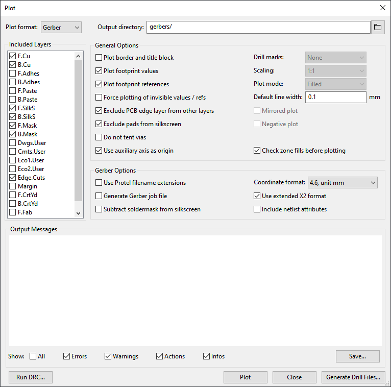
The following is a screenshot of KiCad Plot dialog showing the correct settings.

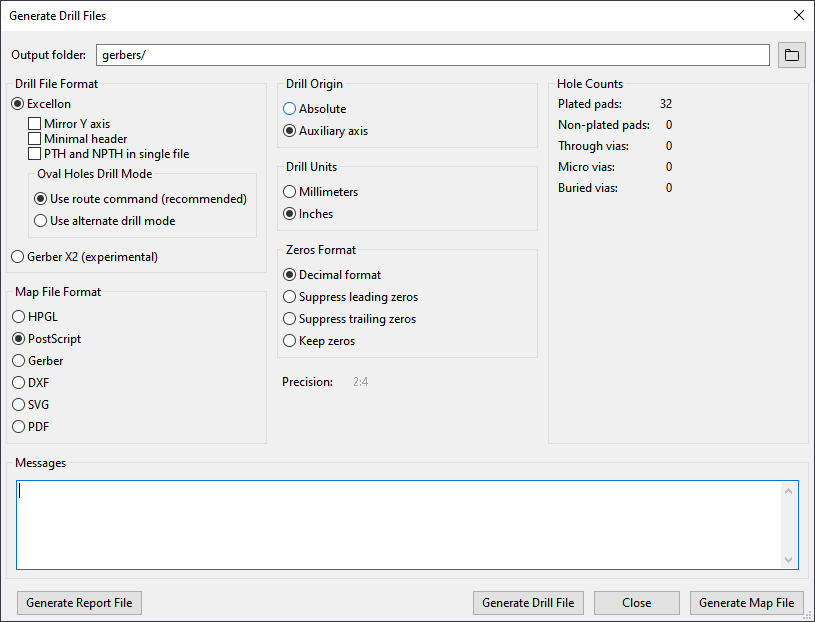
The following is a screenshot of KiCad Generate Drill Files dialog showing the correct settings.

Step-by-step
- Open your design in Pcbnew.
- Select Place -> Drill and Place Offset to place the auxillary axis origin at the bottom left corner of the board.
- Select File -> Plot… to open the Plot dialog.
- Choose Gerber as the Plot format.
- Set the output directory to something meaningful, such as, gerber/
- Make sure the following layers are included:
- F.Cu, Front copper layer
- B.Cu, Back copper layer
- F.SilkS, Front silkscreen
- B.SilkS, Back silkscreen
- F.Mask, Front solder mask
- B.Mask, Back solder mask
- Edge.Cuts, Board outline
- Under General Options, only the following options should be selected:
- Plot footprint values
- Plot footprint references
- Exclude PCB edge layer from other layers
- Exclude pads from silkscreen
- Use auxilary axis as origin
- Check zone fills before plotting
- Set Default line width to 0.1 mm.
- Under Gerber Options, only the following options should be selected:
- Choose 4.6, unit mm for the Coordinate format.
- It’s probably a good idea to click Run DRC… one last time before generating the files.
- Click Plot to generate the Gerber files.
- Output Messages should indicate that a plot file was created for each of the layers.
- Click Generate Drill Files… to open the Generate Drill Files dialog.
- Make sure the Ouput folder is the same as the Gerber output directory.
- Select Excellon as the Drill File Format.
- None of the checkboxes should be checked under Drill File Format.
- Select Use route command under Oval Holes Drill Mode.
- Select Auxilary axis under Drill Origin.
- Select Inches under Drill Units.
- Select Decimal format under Zeros format.
- Click Generate Drill File to generate the drill files.
- Messages should indicate that two drill files were created. One for plated through holes and one for non-plated through holes.
- Click Close to close the Generate Drill Files dialog.
- Click Close to close the Plot dialog.
- Select File -> Save to save the plot settings.
- A zip file can now be created with all the files that were generated in the output directory.

